Minimal Heated Print Bed For My 3D Printer
Posted on November 27th, 2013 by George Moore
Why Build a New Heated Print Bed?
Now, that’s a question I’ve been debating with myself for quite a while. Well, last week, I bit the bullet and sat down to consider the pro’s and cons properly and concluded that the loss of print time and stress of machine reconstruction were definitely outweighed by the potential benefits:
- Reduced heat-up time
- Easier bed levelling
- Simpler construction
- Lighter print bed assembly
- Larger print area
- Better print adhesion
It’s true I could have followed the herd, bought a printed circuit heated bed, assembled it, slapped some glass on it, covered said glass with kapton tape, slobbered ‘ABS juice’ – ABS filament dissolved in acetone- all over it, turned up the heat and hoped for the best. I could have but I didn’t because it seemed to me an over complicated, messy and ultimately pricey way to go. Add to that the potential health implications of messing around with acetone on a hot surface. No thanks!
Getting Prepared
Well, the first step was to source the materials I would use for the heated bed and identify which tools I would use to make it. I hate buying new stuff if I can use what I already have so I had a bit of a rummage in the workshop. After some searching and pondering, I had collected a selection of suitable materials. These were:
- Aluminium Flat Bar 100mm x 150mm x 5mm (1 0ff)
- Aluminium Square Bar 10mm x 10mm x 150mm (1 off)
- Arcol HS25 10Ω aluminium housed resistor (4 off)
- 100kΩ Themistor (1 off)
- 18AWG hookup wire
- M3 X 30mm socket head screws (3 off)
- M3 Nuts (3 off)
- Compression Springs length 25mm diameter 10mm (3 off)
- MDF sheet 160mm x 160mm x 6mm (1 0ff)
- Flux core electronic solder
- Thermal Paste
- Kapton Tape
- Wire Crimps
- M3 x 6mm socket head screws (8 off)
The tools I used were:-
- Milling machine (Mini-mill I converted to cnc a couple of years ago. )
- Machine vice
- Bench Drill
- 2.5mm drill bit
- 3mm drill bit
- M3 Taps
- 7mm drill bit
- 20mm end mill
- Hammer
- Centre punch
- Steel rule
- Hacksaw
- 3mm allen key
- Torpedo level
- Dividers
Making the Heated Print Bed.
Having gathered together all the bits I needed, I set about making the heated print bed.
As the machine vice was too narrow to hold the 100mm wide flat bar for facing off, the first thing I needed to do was figure out how to clamp it. The quickest and most effective way, I decided, was to drill and tap 3 through holes to take M3 screws on the centre line of the plate and screw on a piece of machined 10mm x 10 mm square bar, upon which the machine vice could be clamped. This allowed the full surface area of both faces of the plate to be machined flat by removing 0.5mm from each face, reducing the plate thickness to 4mm. All edges of the plate were machined too, while the plate was clamped in the mill, but this was aesthetic rather than functional. Clamping holes were plugged once machining was finished.
I decided, after a bit of research, I was going to use three point location with the new heated print bed. With this in mind I marked out, centre punched, drilled and counter-bored clearance holes for M3 socket head screws in both ends of one long edge of the plate and one in the centre of the opposite edge.
Once the plate was fully machined, I set about marking out hole locations for the resistor screws on the underside of the plate. These were located so that each resistor, when clamped in place would heat an equal volume of the aluminium plate. Two holes would also be drilled centrally on the plate to accept the 100kΩ thermistor and it’s retaining screw. Once marked these holes were centre punched and drilled with a 2.5mm drill – M3 tap size – to a depth of 3.5mm on the bench drill. All holes apart from the central thermistor hole were then threaded with an M3 x 0.5 tap.
Thermal paste was applied evenly to the mounting face of the four resistors. The resistors were screwed down onto the heated bed plate, taking care to alternately tighten the fixing screws, then wired in parallel with 18AWG hookup wire. The wires were extended to a connector block ready for connection to the megatronics board later.
Taking the 100kΩ thermistor, I carefully insulated the bare wires with kapton tape, leaving the ends uninsulated to allow crimping on the extension wire back to the megatronics board. The extension wires were connected with crimps and insulated with heatshrink. The legs of the thermistor were bent at a right angle just below the thermistor bulb, placed either side of the clamp screw hole and clamped in place with the clamping screw so that the thermistor bulb was held securely in the hole provided. The legs of the thermistor are protected and insulated by clamping them in a sandwich of fibre washers between two metal washers.
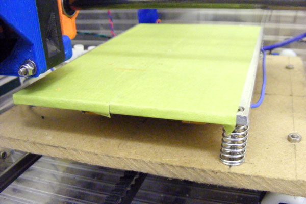
With all wiring in place, I mounted the heated print bed on to the printer’s Y axis sub table using the 3 mounting points with springs under the socket head screws to allow for adjustment, expansion and hotend crashes. I then connected the extension wires to the megatronics board, ready for set-up.
Setting up the Heated Print Bed
With all wires connected, I booted up RepetierHost and powered up the printer. My first check was to see if the heated print bed thermistor was reading room temperature which it was. With that established, I sent a command to the printer to heat the bed up to 100°C. Touching the heated print bed indicated that it was indeed warming up. Quite quickly it had reached the requested temperature without any sign of flames, smoke or nasty smells. All good so far. I left it running for an hour to ensure it maintained temperature. No problem other than a slight temperature swing of 2 degrees probably due to the Bang Bang temperature control selected in the Marlin firmware. I remedied this quickly by uncommenting
#define PIDTEMPBEDin Marlin and re-uploading the firmware. I then ran an 8 cycle PID autotune using
"M303 E-1 C8 S100"in RepetierHost. I then input the calculated values into the Marlin firmware. After uploading the firmware to the printer again, the temperature swing of the heated print bed had been reduced to an imperceptible level.
With all tests complete, it was time to commit to a test print of a 20mm calibration cube. I applied 3M Green Masking Tape to the heated print bed to aid adhesion, then levelled the bed with the torpedo level and set the Z axis homing height with a feeler gauge between hotend and heated print bed. I started the print and 10 minutes later I had a successfully completed calibration cube with no warping. It was also surprisingly well adhered to the heated print bed.
So, does it work?
Yes. Very well I might add. The main improvements over my old heated bed are:-
- Heat up time reduced from over 20 minutes to 7 minutes
- Can now easily reach and maintain 100°C.
- Maintains temperature closer to set point even with cooling fan running.
3D Printer News
Unfortunately due to some mechanical issues with the printer axes, unrelated to the new heated bed, I am unable to print at the moment. I hope to remedy this over the next few weeks so I can get back printing. When I do I’ll hopefully have some more mods to blog about. Looks like I’m going to be a busy fella 😉 .
Please comment on this post as your insights or questions are appreciated.