Adjustable Hobbed Bolt For My 3D Printer
Posted on February 3rd, 2014 by George Moore
Background
In my last post, I described why and how I had made a new heated bed for my 3d printer . I thought once this was built it would be full steam ahead on the 3D printing front. Well it was, sort of, prints were stuck down so hard you couldnt knock them off with a hammer and chisel. Unfortunately while adhesion was sorted, print completion was another matter. After several failed prints I decided to get my problem solving hat on again and see if I could find and fix the problem.
After close observation of the extruder during printing and close inspection of the hobbed bolt on disassembly of the extruder, I uncovered the root cause of my issues. The filament was not centered in the groove on the hobbed bolt and was being driven by the corner of the groove. This tiny contact area was just about capable of driving the filament at printing speed when the teeth were clean but the teeth would gradually grind into the filament and fill up the teeth. Once this happened, usually a few layers into the print, the filament would slip and extrusion would cease.
My first attempt at fixing the problem was to use stacks of washers and spacers to more closely align the centre of the groove with the centre of the filament. This worked, after a fashion, as I was actually able to complete quite a few prints before the hobbed bolt needed to be removed and cleaned. The continued filament grinding and resultant loss of printing time/disruption of settings, even though less frequent, coupled with the occasional panic of dropping/losing the washer/spacer stack made my decision easy.
I must make an adjustable hobbed bolt.
Getting Prepared
Well, the first step was to source the materials I would use for the hobbed bolt, which was fortunately much simpler than it had been for the heated print bed and identify which tools I would use to make it. As the extruder was sized for an 8mm hobbed bolt, I decided that I would go with this size for the replacement. With that decided I collected up my materials. These were:
- 8mm Mild Steel Round Bar 84mm long(1 0ff)
- M8 Lock Nuts (4 off)
- M8 Plain Washers (6off)
The tools I used were:-
- Metal Lathe
- 3 Jaw Chuck
- HSS Turning Tool
- M8 Die
- M6 Tap
- Die stock
- Jacobs Chuck
- Steel rule
- Hacksaw
- Second Cut File
- 240 Grit Emery Paper
- 13mm spanners (2 off)
Making the Adjustable Hobbed Bolt.
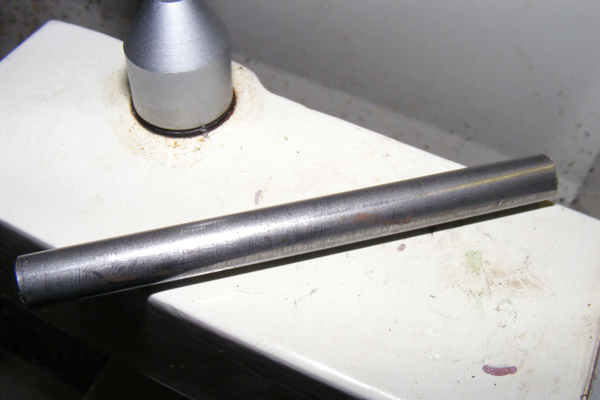
Having gathered together all the bits I needed, I set about making the adjustable hobbed bolt.The first step was to cut an 84mm long piece of mild steel round bar, with the hacksaw, taking care to remove the sharp corners with a quick rub of the file. This piece of bar was clamped firmly in the 3 jaw chuck on the lathe so that 54mm protruded from the chuck. This allowed for 2mm facing off, 30mm of m8 thread, 20mm of centre section, 2mm clearance from chuck.
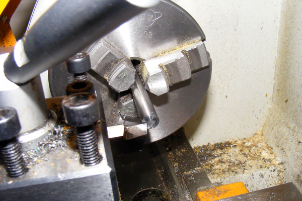
The HSS cutting tool was set up in the toolpost at the centre height of the bar and the toolpost was angled slightly to allow more clearance at the cutting tip for facing off the end of the bar. I started up the lathe and took a quick, light facing cut off the end of the bar, to check I was at centre height. As a small pip was left in the centre of the bar, I knew I was below centre height. To remedy this I added another shim under the cutting tool and took a second facing cut to confirm I was on centre. I then faced off the bar to the correct length.
Even though the bar was nominally 8mm, it would not fit through the 8mm inner diameter bearings used in the extruder. Additionally from my experience cutting threads, it’s much better for the maximum diameter of the thread to be slightly less than nominal size, to avoid cracking the thread cutting die. With this in mind, I turned the bar diameter down by 0.1mm. This had an added benefit of ensuring the bar was round in cross-section rather than oval as rolled in the steel mill. Once the turning was complete, I turned the toolpost so that the tool was angled at 45, reversed the rotation of the lathe and moved the tool behind the bar so that I could chamfer the sharp edge of the bar slightly (I have a history of nasty cuts from sharp edges left on tools, materials and products by unscrupulous manufacturers, so it’s a bit of a must for me).
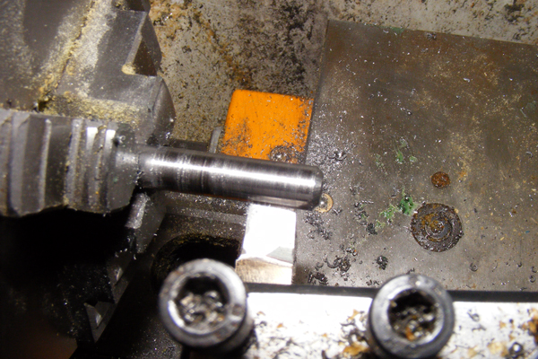
Having finished using the cutting tool for the moment, I moved it out of the way and put the jacobs chuck in the lathe tailstock. Measuring 30mm from the end of the bar, I made a mark with the scriber all round the circumference at that point, as a guide for thread length. With the die placed in the die stock, I centred the die onto the end of the bar and applied pressure to the back of the die stock with the jacobs chuck held in the tailstock to keep it perpendicular to the bar. Turning the 3 jaw chuck by hand (lathe safely interlocked to prevent it starting) whilst maintaining pressure with the tailstock, I let the die cut the thread onto the bar by resting the diestock handle on the lathe saddle. Once the die had cut in past the end of the bar, I moved the tailstock out of the way. I quickly cut the remaining thread to the marked 3omm, reversing the direction of cut frequently to clear the chips from the cutting edges of the die. I gave the threaded and unthreaded sections a quick rub of emery paper with the lathe running to remove any possible roughness or sharp edges on the threads.
Reversing the bar in the lathe with 40mm protruding from the chuck and the machine parts of the bar protected with paper, I faced off the end of the bar and turned its diameter to size as I had done for the rest of the bar previously. With this completed, I proceeded to cut the thread for a distance of 30mm as before, before finishing with the emery paper.
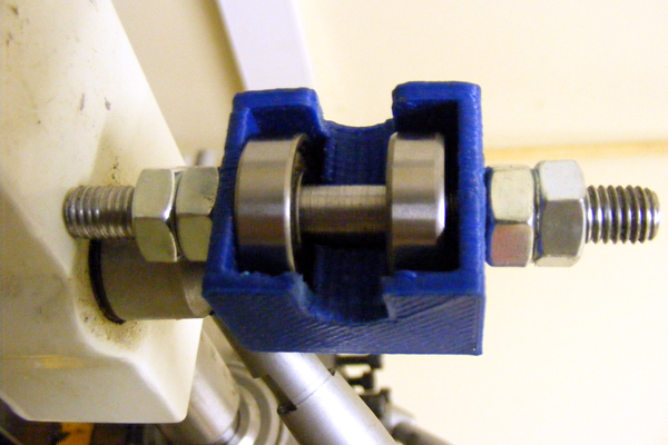
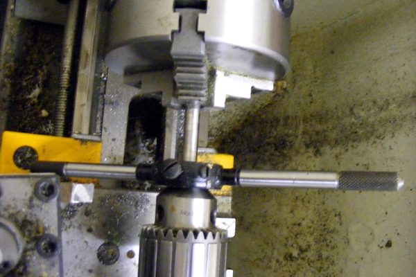
At this point the bar was ready to be hobbed, so it was removed from the chuck and an M6 tap clamped firmly in its place. Placing the hobbed bar into a 3D printed hobbing tool I had fixed in the toolpost, I centred the unthreaded centre section with the centreline of the tap in the 3 jaw chuck. Once located I secured it in place with two pairs of lock nuts such that it was free to turn under the cutting action of the tap without moving lengthwise too much.
Once set up I started the lathe at its slowest speed and carefully moved the bar into contact with the tap so that it began to turn on its axis. I let the tap cut at this depth for a few rotations of the bar before increasing the depth of cut gradually to give the full hobbed tooth profile. Again I left the tap cut at the full tooth depth for several rotations of the bar to ensure even teeth. One thing I learned however was not to let the tap too deep as it can generate flats instead of teeth and a useless piece of scrap instead of a nice adjustable hobbed bolt.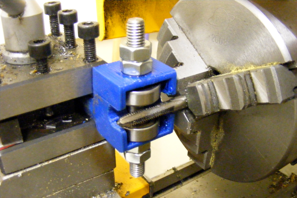
Now that the teeth were cut I removed the hobbing tool from the lathe toolpost, to allow easier removal of the hobbed bolt. As the hobbing process tends to raise the edges of the hobbed groove, these require leveling before the bolt can be removed from the tool. This is accomplished by rotating the bolt slowly with one hand while running a flat file lightly over the hobbed groove with the other. Care should be taken that the file cuts evenly from both raised edges and consistently around the circumference of the bolt so that no flat spots are created.
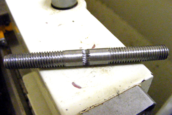
With the manufacture of the bolt complete it was time to install it in the extruder.
Setting up the Adjustable Hobbed Bolt.
Firstly, I removed the old hobbed bolt from the extruder and gave the extruder a quick spring clean to remove any ground filamentand other detritus. With this complete, I pressed a nut into the extruder drive gear and threaded this combination onto the hobbed bolt. I placed five washers behind the drive gear to ensure correct alignment with the stepper motor gear once fitted. The assembly was then carefully inserted into the two extruder bearings and a retaining nut was lightly threaded onto the opposite end of the hobbed bolt. To adjust the alignment of the hobbed groove with the filament guide hole in the extruder, I inserted a short straight filament offcut into the filament guide hole so that it would lay in the centre of the hobbed groove when the bolt was in the correct position. With the drive gear locked in position by the motor gear, the hobbed bolt was unscrewed/screwed until the groove was aligned.
With the hobbed bolt in the correct location a lock nut was carefully tightened against the nut in the drive gear, to ensure its position on the hobbed bolt was secured permanently. The retaining nut on the opposite side of the extruder was then tightened enough to remove any axial movement of the hobbed bolt without locking up the bearings. A lock nut was then tightened tightly against the retaining nut to ensure that it would not unscrew during printing. Without any filament inserted, I ran the extruder motor using the printer host software, to check everything was moving as it should without resistance or nasty grinding noises. The extruder dry run went off without a hitch so it was now time to load up with filament and see how the new adjustable hobbed bolt would work during a proper print.
So, does it work?
Yes. The adjustable hobbed bolt has now been installed for a month and has been working well. Prints have failed for several reasons in that time but none were due to filament slipping/grinding by the hobbed bolt. (Homing and slicing issues seem to be the majority in fact). So I’m pretty happy with my new setup.
The main improvements over my old hobbed bolt are:-
- Adjustable enough to allow for design changes, machining variations, etc. yet stay centered on the filament
- No filament grinding / teeth cleaning ( I did have to clean the hobbed bolt once but that was due to a hot end blockage stopping the filament dead in its tracks.)
3D Printer News
As mentioned in my post, Minimal Heated Print Bed For My 3D Printer, I had some mechanical issues with the z-axis of the printer which I temporarily solved with some creative hacking using a piece of dowel & some woodscrews. This held together long enough to allow me to print some replacements/improvements, namely nophead‘s Z-axis coupling.
In other news, I have started trying to master Openscad. I figured it would be useful as it seems to have become the default for editable 3d printing files in the opensource community. Will hopefully be able to share some of my learnings in future blogposts.
Finally, design work continues apace on my new 3d printer. I’m pretty happy with my current 3d printer’s performance at the moment but it’s distinct lack of portability and persistent z ripples due to a lack of structural stiffness are driving the new design.I will regular post updates on the progess on the new printer, which hopefully I will start building in the next few weeks, if i can just stick to my new years resolution of blogging more regularly, not just on a blue moon ;).
Please comment on this post as your insights or questions are appreciated.